
An owner of one of these decided to swap the 13A plug for a Commando one, only to discover after cutting it off that there are 6 wires going into the plug! I acquired this, and have repaired it with a chunky new 13A Masterplug and have fitted the 2 thermistors inside where they belong. I'm posting what I've learned so as to help anyone else with a damaged/destroyed plug, or wanting to do the same kind of plug-swap, so they can buy they correct valued thermistors if required.
The original owner carefully disected away the plug, and rescued both thermistors & the fragments of wire, enough for me to be certain of the connections. Thank you!
In addition to the usual 3 wires, the cable from the EVSE has 3 more coloured Black, Purple/Grey, and Purple/Black.
One thermistor is connected between Black and Purple/Black.
One thermistor is connected between Black and Purple/Grey.
The black wire appears to be the common return/ground for these, as both white leads on the thermistors are soldered together with the black wire.
I believe the thermistors to be Vishay NTCLE100E3103 which are 10k Ohms at 25C. Colour code Brown-Black-Orange.
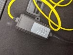
Type-2 plug EVSE (from a Bmw, probably i3) with new plug fitted:

Underside of EVSE:

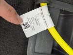
Wire fragments:

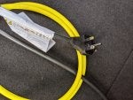
13A Masterplug

A very small amount of trimming was needed inside the Masterplug to not trap the thermistor wires. In the Rhs view one thermistor has been tucked beside the Neutral wire, and the other thermistor sits above the fuse.
I checked the resistance of the 2 thermistors carefully, letting them cool slowly from 100C on my K-thermocouple-controlled Heated Base Plate. I believe the thermocuple temperature will have been at most 2 degrees C cooler than the thermocouple reported, and that reports in 1C intervals. So there's a fair bit of variation in the resistances I measured while the temp controller (an industrial Toho unit) was reporting a single temperature.
Here's a table of the max and min resistances (Ohms) I measured at a series of temps, and also the nominal resistance expected from a Vishay NTCLE100E3103 thermistor datasheet:
Temp Min Max NTCLE100E3103
100 707 759 677
95 800 847 786
90 908 957 915
85 1046 1099 1070
80 1224 1294 1256
70 1680 1768 1753
60 2380 2502 2490
50 3437 3556 3605
40 5044 5353 5330
30 7470 7800 8059
25 9187 9675 10000
24 9642 10110 (no data)
Given the variability in thermistors (the 2 I tested were usually about 30 Ohms apart, and must have been near-as-dammit identical temps) I consider this a pretty close match, certainly accurate enough for this Vishay thermistor to be used as an excellent replacement for a damaged original. My thanks to Farnell (& Cpc, part of the same group) for making the datasheets & parts available.
The original owner carefully disected away the plug, and rescued both thermistors & the fragments of wire, enough for me to be certain of the connections. Thank you!
In addition to the usual 3 wires, the cable from the EVSE has 3 more coloured Black, Purple/Grey, and Purple/Black.
One thermistor is connected between Black and Purple/Black.
One thermistor is connected between Black and Purple/Grey.
The black wire appears to be the common return/ground for these, as both white leads on the thermistors are soldered together with the black wire.
I believe the thermistors to be Vishay NTCLE100E3103 which are 10k Ohms at 25C. Colour code Brown-Black-Orange.
Type-2 plug EVSE (from a Bmw, probably i3) with new plug fitted:
Underside of EVSE:
Wire fragments:
13A Masterplug
A very small amount of trimming was needed inside the Masterplug to not trap the thermistor wires. In the Rhs view one thermistor has been tucked beside the Neutral wire, and the other thermistor sits above the fuse.
I checked the resistance of the 2 thermistors carefully, letting them cool slowly from 100C on my K-thermocouple-controlled Heated Base Plate. I believe the thermocuple temperature will have been at most 2 degrees C cooler than the thermocouple reported, and that reports in 1C intervals. So there's a fair bit of variation in the resistances I measured while the temp controller (an industrial Toho unit) was reporting a single temperature.
Here's a table of the max and min resistances (Ohms) I measured at a series of temps, and also the nominal resistance expected from a Vishay NTCLE100E3103 thermistor datasheet:
Temp Min Max NTCLE100E3103
100 707 759 677
95 800 847 786
90 908 957 915
85 1046 1099 1070
80 1224 1294 1256
70 1680 1768 1753
60 2380 2502 2490
50 3437 3556 3605
40 5044 5353 5330
30 7470 7800 8059
25 9187 9675 10000
24 9642 10110 (no data)
Given the variability in thermistors (the 2 I tested were usually about 30 Ohms apart, and must have been near-as-dammit identical temps) I consider this a pretty close match, certainly accurate enough for this Vishay thermistor to be used as an excellent replacement for a damaged original. My thanks to Farnell (& Cpc, part of the same group) for making the datasheets & parts available.

")


